Dear readers,
on October 31st 2020 I attented the first open-box PNN demonstration. I’m writing this post with the goal of sharing the experimental setup and explain it at my best so that the experiment can be replicated independently and the results can be observed, evaluated and measured. I also have some video footage of the experiment but its translation will require me some time, so I’m going to add the videos at a later time.
Edit 05/11/2020 – Added video Explanation of PNN by Emidio Laureti at the end of the post. More videos will follow.
Edit 06/11/2020 – Added video PNN Roadshow Test #1 at the end of the post
Edit 19/11/2020 – Added video PNN Explanation #2 (by another ASPS member) at the end of the post
First of all, since the disclosure represents a turning point in the history of PNN, let’s recap the claims and the issues of this engine so far:
The claims:
- The device generates an usable force as a resultant of the Lorentz forces that act on two arms of a V-shaped dipole
- It’s working principle is based on the concept that the Lorentz forces exist in open circuits too but they’re too weak to be detected. However, through field self-interaction it is possibile to strengthen them and make them appreciable and therefore exploitable.
- The resultant force is a net thrust that can be exploited to propel a spacecraft without expelling reaction mass. At the moment this force is small, but enough to be already competitive with ion engines.
- With enough power and suitable materials that can endure high currents and frequencies, the thrust could be significantly strenghtened as there are wide margins of improvement
- After the engine is turned off, the device doesn’t go immediately to rest, but it remains tilted for some time as if it kept pushing, then it slowly comes back to the starting position.
- Reaction force appears to not be present
The issues:
- Further experiments must be conducted to exclude thermal deformations or other misleading problems. For the moment, the following tests have been conducted (more informations here):
- Put the prototype on a scale and make it generate thrust upward and then downward (that is, the dipole vertex is oriented upward and then downward). The tests detected respectively a weight reduction when the thrust is upward and a weight increase when it’s downward. This could exclude mistaking for thrust a thermal deformation of the coaxial feeding cable when the prototype is on the ballistic pendulum.
- Punch holes in the coverage box to avoid that the air inside that is heated by the dipole might trigger a “blimp”effect: the grey plastic pipes you can notice in the thruster framework are the air outlets. However it seems this eventuality can be ruled out since when the prototype thrusts downward the weight on the scale still increases
- Enclose the prototype in a plastic bag to rule out any movement by hot air currents. The device behavior doesn’t vary.
- The whole setup is, as you can see, made with DIY materials, like wood. There’s the need to rebuild the system with more suitable materials, from the ballistic pendulum to the ferrites, that are the general ones without specifications sold in stores.
- There is a need for specific testing instruments, for example a field detector small enough that can be placed between the dipoles, as close as possbile to the vertex
- Lot of the input power is lost with irradiation and overheating
- The prototype can operate for about one minute, then it must be turned off to let it cool down
Let’s see now the theoretical basis of the invention, the practical realization, the test setup and the test procedure:
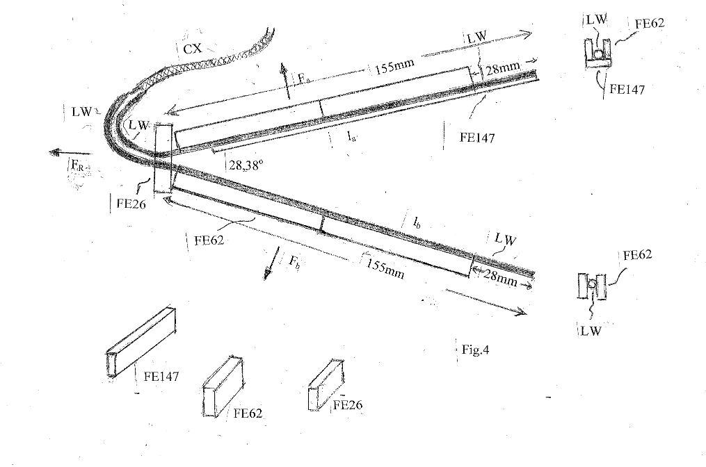
Let a V-dipole be given, powered through a coaxial cable CX with the feedpoint at the center of the two arms A and B as in fig. 1.

The dipole is the thruster itself, what has always been hidden inside the PNN black box:
The grey plastic pipes at the sides were used to exhaust hot air and avoid the “blimp effect”

CX = Coaxial cable
LW = Litz Wire
FE = Ferrites
Fa / Fb = Lorentz forces on arms a / b
FR = Resultant force of Fa and Fb
Given a power supply frequency, the length of the arms must be such that by varying their length, a suitable resonance frequency is found. The angle 2α is the angle at the vertex of the dipole where α + α are the angles formed by the bisector at the vertex angle of the V dipole. The vertex angle can theoretically be of any amplitude between 0 degrees and 180 degrees .

In the experiment setup the input power is a 432 Mhz sine wave at 600W. This is the power control (the tinfoil is to protect the instruments from E.M radiation):

The choice of the angle will be determined by the efficiency of the mutual interaction between the two arms.
We will therefore call the arms of the dipole arm A and arm B. However, the essential thing is that the two arms by emitting electromagnetic waves can interact with each other with the magnetic field emitted in this sense: the e.m. wave. emitted from arm A hits arm B and the e.m. wave emitted by the arm B hits the arm A causing, with the current in the arms as in fig, 2 and fig.3 of the Lorentz forces, that is a self interaction between the 2 open circuits A and B.

Given a power supply frequency, the length of the arms must be such that by varying their length, a suitable resonance frequency is found. The angle 2α is the angle at the vertex of the dipole where α + α are the angles formed by the bisector at the vertex angle of the V dipole. The vertex angle can theoretically be of any amplitude between 0 degrees and 180 degrees .
The choice of the angle will be determined by the efficiency of the mutual interaction between the two arms.
We will therefore call the arms of the dipole arm A and arm B. However, the essential thing is that the two arms by emitting electromagnetic waves can interact with each other with the magnetic field emitted in this sense: the e.m. wave. emitted from arm A hits arm B and the e.m. wave emitted by the arm B hits the arm A causing, with the current in the arms as in fig, 2 and fig.3 of the Lorentz forces, that is a self interaction between the 2 open circuits A and B.
Especially at the vertex of the V where the two conductors spread apart and are closer together, the current and magnetic permeability of the ferrites must be maximized.
As imaginable, the closer you get to the vertex, the stronger will get the Lorentz force. Therefore most of the thrust will be obtained nearby the feedpoint.
The dipole thrust cannot be easily detected at naked eye for two reasons:
- It’s too small to be noticed
- Observers must keep a safety distance from the prototype while in operation to avoid dangerous irradiation (field detector measured 50 V/m at about 3-3,5 meters)
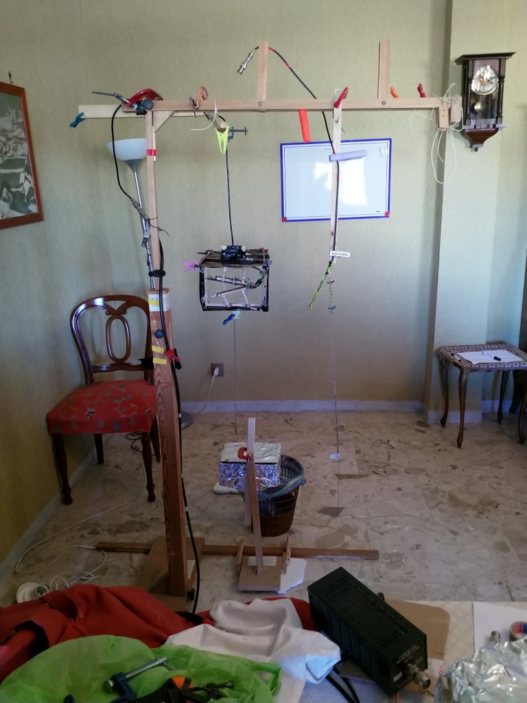
Therefore ASPS adopted this experimental setup:

The thruster is hung on the structure by its power supply cable. Below the device it is attached a 1 meter long rod that will be used as a pendulum. Most of the rod is made out of wood, but the final trait is a metal wire to thin the projected shadow.
The rod terminates at the level of a box wrapped in tinfoil (always to shield the devices from irradiation) where it’s enclosed a laser beam projector.
The laser beam is projected on the wall behind and the pendulum shadow is centered in the middle by adjusting the box position.
Once the device is powered -for about 30” to 1′ – the thrust will be observed through the movement of the pendulum shadow on the laser beam, from left to right.
Once the device is powered off, the same method is used to observe the delay of the thruster in returning to a resting state.

The second test is the observation of the Lorentz force that acts on a single arm by using this setup:

CX = Coaxial cable
LW = Litz Wire
ST = lock for second arm
F = Lorentz force
AS = pendulum rod
LR = laser beam
IR = projected index
In order to evaluate the force exerted on each arm, the system is positioned as shown in figure 5.
In other words, at the exit of the CX coaxial cable, a long rod of non-conductive material is hung from the arm Ia and is positioned vertically in the same direction as the force of gravity and can oscillate due to the flexibility of the Litz Wire while the other arm lb is kept locked with the ST brackets to form an angle 2α with the previous arm.

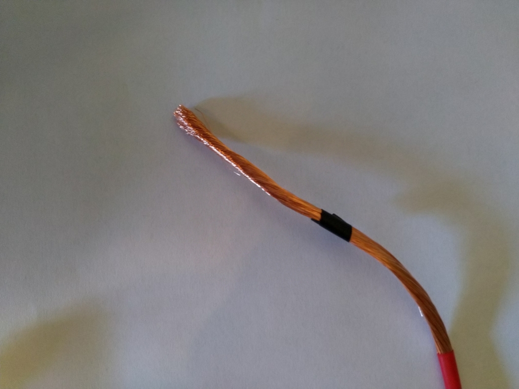
Part of the wire protection of the right arm has been removed to make it more flexible
A string on the left arm keeps it in position.
The test procedure is identical: the dipole is powered for a period between 30” and 1′.
During this period the left arm of the dipole, that is free to move, will tilt to the right according to the direction of the Lorentz force that acts on it. The movement is then observed through the projected shadow of the pendulum on the laser beam.
When the power supply is switched off, the free arm will remain tilted for about 10 minutes, then it will slowly return in position according to the observations made with the thruster.
This conclude the description of PNN, or Field Self-interaction Electromagnetic Thruster as it has been baptized in the patent, and of the testing procedure to detect its thrust.
Please stay tuned for the video footage of the experiment.


Fatto molto bene
Grazie
Emidio Laureti
————
Ad eundum quo nemo ante iit
http://www.asps.it
Da “Neo Leges Motus” comment-reply@wordpress.com A asps@asps.it Cc Data Mon, 2 Nov 2020 18:42:16 +0000 Oggetto [New post] Field Self-interaction Electromagnetic Thruster sergioz82 posted: ” Dear readers, on October 31st 2020 I attented the first open-box PNN demonstration. I’m writing this post with the goal of sharing the experimental setup and explain it at my best so that you can replicate the experiment and observe the results wi”
LikeLike
Grazie 🙂
LikeLike
Reblogged this on SEL-ROC.
LikeLiked by 1 person
..
– Edit Sergioz82:
Perdonami Selroc. Ti ringrazio molto per il tuo contributo ma ho dovuto rimuovere il video per motivi di privacy.
LikeLiked by 1 person
secondo te dovrei rimuovere il video da youtube?
LikeLike
no problem, adesso il video e’ privato e non si vede su youtube.
LikeLike
Nella descrizione relativa alla spiegazione della PNN come forze di Lorentz in un triangolo privato della base ho dimenticato di ribadire che si può fare quando la frequenza della corrente opera appunto a 432 Mhz 🙂 …. con i bracci del dipolo appunto idonei in lunghezza alla frequenza di risonanza 🙂
LikeLiked by 1 person
https://www.internationalwebpost.org/contents/IL_FUTURO_DELL%E2%80%99UOMO_SULLA_LUNA_20179.html#.X8dQPknsYdU
LikeLike
Adesso i gotha vogliono paragonare la pnn al magnetorquer….semplicemente RIDICOLO.
LikeLike
7 Gennaio , 1943
Moriva oggi Nikola Tesla (1856-1943), genio inventore, fisico e ingegnere elettrico, nato nell’Impero austro-ungarico e naturalizzato statunitense. È conosciuto per il suo lavoro in campo tecnico-scientifico e in particolare per i contributi nel campo dell’elettromagnetismo applicato; i suoi brevetti e il suo lavoro teorico formano, in particolare, la base del sistema elettrico a corrente alternata, la distribuzione elettrica polifase e i motori elettrici a corrente alternata, con i quali ha contribuito alla nascita della seconda rivoluzione industriale.
Ha contribuito allo sviluppo di diversi settori delle scienze applicate; i suoi ammiratori arrivano al punto da definirlo “l’uomo che inventò il ventesimo secolo” e “il santo patrono della moderna elettricità”; la sua importanza fu riconosciuta nella Conférence Générale des Poids et Mesures del 1960, durante la quale fu intitolata a suo nome l’unità del Sistema internazionale di misura dell’induzione magnetica.
A causa della sua personalità eccentrica e delle sue affermazioni talvolta bizzarre e incredibili, negli ultimi anni della sua vita Tesla fu ostracizzato e considerato una sorta di “scienziato pazzo” pur attribuendogli talora curiose anticipazioni di sviluppi scientifici successivi.
LikeLike