
Dear readers, it has been a while since my last post but I think it was worth the wait.
Because now, after more than 20 years of study, experimentation and dedication by Laureti and ASPS, it is time to unveil this game changing technology.
Before we delve deeper in its working principle, I want to share a personal consideration: as you will see, this technology is incredibly simple. The word simplicity of course mustn’t be confused with easy. It’s simple when you compare it to all the massive thoughts and efforts that has been put into finding exotic solutions for space travel, like warp drives, dark matter, artificial black holes, solar sails, spacecraft pushed by laser beams and so on. The “humble” PNN instead is, in its core, a v-shaped dipole antenna. That’s it. The thruster can be replicated in any amateur lab. Actually, you’re encouraged to replicate the experiment and make your own observations (always keep in mind that the device emits strong e.m fields and it’s subjected to overheating so take your precautions).
But enough with this chatting, let’s have a look to the description of its working principle, explained by Emidio Laureti (here in Italian):
One of the essential things to understand about the 1998 patent granted in 2000 www.asps.it/pat98.jpg but not developed later are the following:
The two dipoles whose thrust was generated by the interaction of current with the magnetic field according to Lorentz’s law WERE TOO FAR even if only one quarter wave apart.
My suspicion (of an experimental nature but subject to the instrumentation at my disposal) is that the magnetic field propagates in the near zone with a trend of the type 1 / r3 if not even weaker.
This also derives from long discussions never experimentally resolved in which I doubted as I doubt now that the magnetic component of the wave propagated in the free field (far zone).
What I called and call “Maxwell’s ghost” that no one among the staunch Maxwellists has interest to see if it’s there (the apparatus and the experiment is expensive and requires at least experimental space and adequate personnel).
But now it is not necessary to return to this unresolved issues.
After all, I did not have the means to prove “how much magnetic field” and how the magnetic field propagated in the near zone of a half-wave dipole, that is how much intense it was even at distances of a quarter wave.
The only essential thing was that I had to bring the two dipoles of www.asps.it/setupdip.htm as close as possible.
A substantial error on Lorentz forces in open circuits is to consider them null when they are too small!
But the amplification of their effects through the nearing can only be done with self-interaction, i.e. by completely changing the experimental setup of the 1998 patent granted in 2000 by www.asps.it/pat98.jpg which is also mentioned in www.asps.it/pnndatabase.htm
On the sidelines of the concept of self-interaction in electrodynamics I would like to say there are boulders and pyramids of mathematical publications (for me comic theoretical chatters) on the concept of self-interaction but I have never found a publication that said how to carry it out experimentally the self-interaction that is finalized in the push .
This confirms that physics has long been invaded by a philosophical chatter of mathematical extraction that creates hallucinatory visions of the Creation both visible and invisible (distant).
Anyway, the keystone is to always apply up to the yelding of the unknown what no one notices, that is the antennas are open circuits in which the Lorentz law still holds, in which, essential thing, in the wire l in which current i flows, on which affects the magnetic field B normal to the wire (the only useful component of the magnetic field!), and the force F is generated, which can ALWAYS be observed all three perpendicular to each other.
Note that if nature (the Unpronounceable for me) had not made the Lorentz force as it was done, that is, with the so-called 3-finger rule, the PNN would not exist. 🙂
In memory of Lorentz (Nobel Prize) and of the difficulty of using the magnetic field in antennas, it must be said that like me Lorentz thought that the magnetic field of the displacement current propagating in a vacuum did not exist at all.
Therefore, as much as anti-relativistic it may appear, I must unfortunately think that a wave in a vacuum is only electrical (until experimental proof that it is not an experimental error) and that it becomes pure magnetic locally ONLY when it encounters a conductor.
This is anti-relativistic due to the fact that the self-styled vacuum (the old ether for others) absorbs and cyclically transfers energy to the wave. If this were not the case, energy conservation would be violated during the journey.
I have no idea what the structure of the void, or the ether if you like, is … I just know that the Lorentz force exists and is made as it is made.
In the patent filing of F432 different configurations of the thrust systems are described and claimed, that is configurations suitable for increasing the PNN thrust and transforming into advantages what appears to be, in a non-reflective evaluation, inefficiencies.
In ASPS urls that deviate from www.asps.it and www.asps.it/pnnecommerce.htm further info will be put online in which the PNN box CLOSED AND OPEN shown further data on the know-how of the PNN of F432…. But I don’t know the timing of this yet. Probably something will also appear in Nova Astronautica n. 166, vol. 40 2020 as in “press releases”.
And now let’s move on to the essential details of the Experimental PNN unveiled after about 20 years!
Essential info will be given on how to replicate basic PNN experiments if you have a lab with at least 500 watt power amplifiers and various accessories that I leave to your imagination :-).
FIELD SELF-INTERACTION ELECTROMAGNETIC THRUSTER
Introduction
It is described a propulsion system that with variable currents and through the reciprocal electromagnetic interaction of some of its parts on other parts of it produces a thrust resultant in the same direction and verse without expulsion of the reaction mass.
Let a V-dipole be given, fed through a coaxial cable CX with the feedpoint at the center of the two arms A and B as in fig. 1.

Given a power supply frequency, the length of the arms must be such that by varying their length, a suitable resonance frequency is found. The angle 2 alpha is the angle at the vertex of the dipole where alpha + alpha are the angles formed by the bisector at the vertex angle of the V dipole. The vertex angle can theoretically be of any amplitude between 0 degrees and 180 degrees .
The choice of the angle will be determined by the efficiency of the mutual interaction between the two arms.
We will therefore call the arms of the dipole arm A and arm B. However, the essential thing is that the two arms by emitting electromagnetic waves can interact with each other with the magnetic field emitted in this sense: the e.m. wave. emitted from arm A hits arm B and the e.m. wave emitted by the arm B hits the arm A causing, with the current in the arms as in fig, 2 and fig.3 of the Lorentz forces, that is a self interaction between the 2 open circuits A and B.


The magnetic field of the variable current ia circulating in arm A will cause a magnetic field Ba incident normally on the long arm lb and therefore a Lorentz force of type Fb = ib lb Ba normal to the arm B where current ib flows. The vector of this force Fb lies in the plane determined by the two arms of the V dipole. Identically, the magnetic field Bb of the variable current ib circulating in the long arm lb will determine a magnetic field normally incident on the arm la where current ia flows and therefore a force of Lorentz of type Fa = ia the Bb normal to arm A. The vector of this force lies in the plane determined by the two arms of the V dipole.
The two magnetic fields incident on the arms are normal to the plane determined by the arms.
Both forces in each half cycle of the oscillating current, and in all those in sequence, will always be repulsive to each other or tend to increase the angle at the vertex of the V-dipole and directed towards the outside of the arms and normally to the arms.
Assuming that in module Fa and Fb are equal to F, the resulting force Fr will be 2Fsen (alpha) and will be directed in the direction of the bisector in the direction that goes from the angle 2alpha to the external corner where the angle is greater than 180 degrees.
In all cycles of oscillation of the current in the dipole Fr = 2Fsen (alpha) Fr is therefore the resulting force vector of two vectors Fa and Fb acting along the direction of the bisector with a direction from the inner to the outer corner of the V dipole as indicated in fig. 2 and fig. 3
Each arm of the V system is made with conductors made up of many thin enameled wires tightened in parallel like Litz Wire LW in order to lower the impedance. Also for the purpose of lowering the impedance, ferrites are positioned along each arm.
Ferrites also have the task of changing the magnetic permeability of the interaction zone in order to intensify the magnetic fields and therefore the magnetic-type forces on the arms and have a resultant with greater thrust.
Especially at the vertex of the V where the two conductors spread apart and are closer together, the current and magnetic permeability of the ferrites must be maximized.
The propulsion system will therefore be more efficient if the impedance is lowered in order to have more current in the two arms and more powerful magnetic fields. Suitable ferrites must therefore be used to get what is needed.
In general, in order to have the smallest phase difference between currents and magnetic fields on the tail of the arms (far from the feedpoint), it is necessary to …….
(OMISSIS FOR PATENT RESERVE)
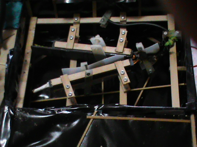
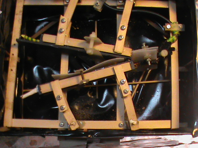
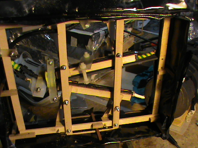
Figure 4 describes a V-shaped thruster with an angle of 28.38 degrees between the arms, with ferrites allocated on the arms and with arms 155 mm long and formed by Litz Wire and operating frequency around 432 Mhz.
Fig. 4 describes the ferrites and how they are mounted on the arms.
To keep the ferrites hooked to the arms, appropriate “brackets” are used (OMISSIS)
THRUST MEASUREMENT TEST
In order to evaluate the force exerted on each arm, the system is positioned as shown in figure 5.
In other words, at the exit of the CX coaxial cable, a long rod of non-conductive material is hung from the arm Ia and is positioned vertically in the same direction as the force of gravity and can oscillate due to the flexibility of the Litz Wire while the other arm lb is kept locked with the ST brackets to form an angle 2α with the previous arm.
Of course, everything must be calibrated well and the following fundamental distinction must also be remembered: measuring a force in a Newtonian regime is not the same as measuring it in a NON-Newtonian regime.
………… OMISSIS due to patent reserves ……….

FINAL CONSIDERATIONS (for now 28 October 2020)
A reflection that for me is more comic than serious.
For years the scientific community has been prey (and perhaps still is) to discussions about the functioning or not of the emdrive (This trap is hilarious it basically represents the only attempt to build an engine without knowing how it works 🙂 something that has no historical traces in physics and / or engineering 🙂
… in the light of the PNN its eventual thrust is in my opinion completely random because it is enough to see the chaotic data and the magnetic fields on what is called “cup”. Now, where there is local magnetic field there is current and there is also, coincidentally, local currents open on closed surfaces (in detail there are many parts of chaotic open circuits) especially on angles (sharp or obtuse or straight edges) of the ends of the truncated cone of the cup. 🙂
What do I mean? that if there was a thrust it was always determined between INTERACTIONS between open circuit currents and interaction based on the Lorentz force or rather the resultants of force vectors with an unknown number of potential circuits.
As I have said many times, from my point of view (of which I have never given the above details) the emdrive looked like an inefficient, chaotic, random PNN with square wheels 🙂
On the basis of what has been described above about the PNN know-how of which a patent has been filed, different types of PNN engines have been developed over the course of 20 years (in total at least 11)…. of which the last called PNN “SUBITAM CLASS “could theoretically take off from the ground if it also had other expensive and ESSENTIAL details, such as a nuclear reactor as primary power supply for electricity.
The “Subitam” or the SUPERPOWERED PNN F432 could colonize the Moon and Mars if we gave up wasting time and money with arthritic missiles similar to cyclopean suppositories losing reaction mass in an inevitably catastrophic way during the journey.
Space is colonized only by overcoming Newtonian mechanics with faster spaceships, which change all 3 of Newton’s principles … because obviously by changing the principle of action and reaction also the other two Newton’s principles change.
Only with enhanced reactionless propulsion systems one can build a spaceship that DOES NOT LOSE MASS.
With PNN SUBITAM we at Space Propulsion Development Association have a certain advantage before the competition can understand how F432 thrust should be enhanced. I translate: the time window to achieve it through ASPS with competitive advantages (patent aside) will not be open for long …. Otherwise may the best WIN and, excuse me for the detail, we can FINALLY pee permanently (a substantial difference between us and robots!) On the Moon and on Mars :-)….

aggiungo un commento fatto privatamente a me E.Laureti …. che mitigherò nelle espressioni folcloristiche :
un commento divertente che ho ricevuto …..
” ……affascinante ed anche esilarante:
ora capisco (scrive anonimo che se vuole può qualificarsi ) perché ti han sempre fatto ridere i tuoi detrattori, gli emdrivisti ed altri fisici in genere.
La tua invenzione porrà loro molti quesiti imbarazzanti.. primo fra tutti come hanno fatto a farsi scappare da sotto il naso un fenomeno del genere che da quanto ne posso capire poteva essere scoperto già ai tempi di Marconi.
A me vien da ridere se penso a tutte le pip…… mentali che si fanno da decenni a proposito di curvature, materie oscure, plasmi quantici virtuali etc ……………. ” 🙂
Mio commento:
alle università quelli ritenuti migliori sono i più imbecilli 🙂
ottusi e idioti inabili all’osservazione fisica … rincoglioniti fuori scala … dalle impressioni visive matematiche 🙂
ovvero come purtroppo ho sempre detto ai detrattori storici di riferimento della PNN http://www.asps.it/gotha.htm …
ve l’ho detto un miliardo di volte che non capite un k……. ! 🙂
LikeLike
😀
Sì, riflessione mia sulle implicazioni direi “morali” di questa invenzione.
LikeLike
a margine vorrei inserire un commento fatto a un formalista delle
gothalist (sono 3) … sedicente gabolatore Leonardo Serni http://www.asps.it/gabolas.htm
ecco il commento
” ….trovo naturale ribadire continuamente il relativismo totale del linguaggio
se vuoi puoi leggerlo come : me ne frego delle regole …..
sai …..non si sarebbe trovata la pnn seguendo le vostre esilaranti
“regole” 🙂 ….. “
LikeLike
Sono iscritto a asps dal n° 1 circa da 40 anni e finalmente ho capito come funziona la PNN. In effetti in una antenna la corrente alternata va avanti e indietro e provoca l’emissione di onde EM però attorno all’antenna c’è un campo magnetico pure variabile alla stessa frequenza e ovviamente in fase con la corrente e se si riesce, come voi avete fatto , a sfasare le correnti dei due bracci in angolo di 180 gradi i bracci si respingono e nasce questa famosa spinta PNN. Il problema è che una astronave nello spazio è un sistema isolato e se la astronave riceve una spinta in una direzione contemporaneamente nasce una spinta uguale nella direzione opposta. Le due uniche possibilità di funzionamento è che le onde EM emesse funzionino come un motore a reazione con espulsione di massa oppure che lo spazio vuoto non sia vuoto ma pieno di energia (il famoso etere potrebbe essere la massa oscura e l’energia oscura che riempono circa il 90% dell’universo) e allora la astronave avanzerebbe perchè si appoggierebbe all’etere (esattamente come una elica sotto l’acqua). Naturalmente lo stesso etere farebbe da freno come l’aria frena una automobile, a meno di riuscire a togliere l’etere davanti all’astronave o a farlo scivolare ai lati ma qui il problema diventa difficile.
LikeLike